Self-Aligning Feature of Insert Ball Bearing Units: How Much Misalignment Can UCP Tolerate?
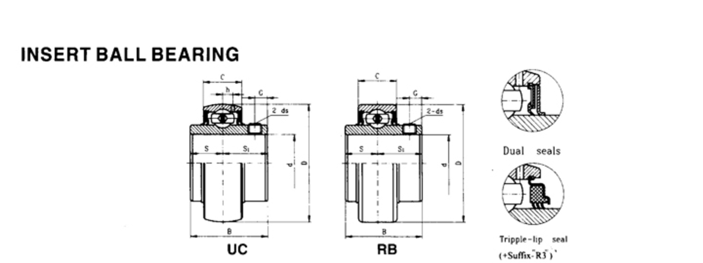
Insert-bearing units can self-align because the outside of the insert is spherical and the housing bore is machined to a matching spherical seat. That allows the insert to tilt relative to the housing and compensate for modest errors in the mounting surface or shaft line.
The important engineering point is that self-alignment is a correction feature, not permission to design a bent or badly misaligned shaft. The design does not establish one universal angular limit across every UCP configuration.
How the spherical seat works
The insert outer ring can orient itself inside the housing seat so the rolling elements are not forced to follow a small housing-mounting error. This is especially useful on fabricated frames, conveyors and agricultural equipment where two bearing supports may not be machined in one rigid precision housing.
Why a universal “±2°” rule is unsafe
Some planning references use a small angular figure as a practical illustration, but allowable misalignment depends on seal design, housing geometry, shaft conditions, speed and the specific product. Because the supplied product data does not establish a universal angle, do not use one number as a design limit without configuration-specific technical confirmation.
Angular misalignment vs parallel offset
Self-alignment addresses angular error between the bearing insert and housing. It does not move the shaft centreline to correct two supports that are laterally displaced. Parallel offset can bend the shaft or force each bearing to operate at an unintended angle even if the spherical seat can tilt.
Shaft deflection is a different problem
A heavily loaded shaft can bend between supports. The insert may align with the local shaft angle, but the bearing still sees the load created by that deflection. Excess shaft bending can reduce bearing life, damage seals and disturb couplings or driven components.
Anti-rotation feature
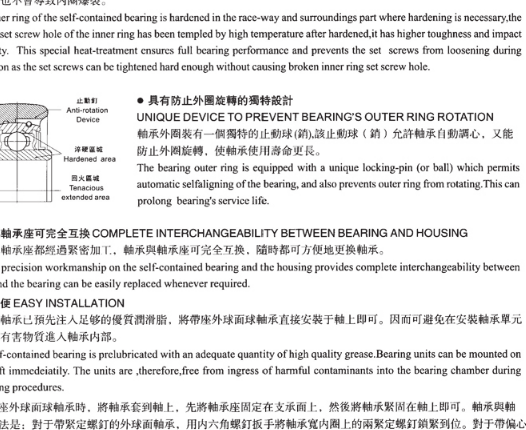
The supplied bearing-unit construction also shows an anti-rotation pin/ball arrangement on applicable inserts. Its role is to prevent the outer ring from rotating in the housing while still allowing the self-aligning seating action. Do not remove or defeat that feature during service unless the specific product instructions require otherwise.
What to check on a misalignment problem
| Observation | Engineering check |
|---|---|
| Housing faces not coplanar | Correct frame / mounting surface before relying on self-alignment |
| Shaft hard to turn after bolts tightened | Loosen and realign supports; inspect base flatness |
| Repeated hot bearing on one side | Check shaft line, pulley/coupling alignment and load reaction |
| Seal rubbing or leakage | Check tilt, shaft position and seal condition |
| Bent shaft | Repair/replace shaft; self-aligning housing is not the primary fix |
Angular and parallel misalignment are not the same
The spherical insert / housing interface can accommodate a limited angular difference between the shaft and housing. It does not move the shaft sideways to correct parallel offset between two supports. If two housings are mounted on bases that are laterally displaced, the shaft can still bend or load the bearings even though each insert can tilt slightly.
Self-alignment is not a substitute for shaft stiffness
A long or heavily loaded shaft may deflect under operating load. The insert can follow some angular change at the housing, but the rolling elements still see the consequences of load distribution and changing shaft angle. Severe deflection should be addressed through shaft design, support spacing or machine structure, not by relying on the self-aligning feature.
Verify the actual model limit
The planning reference discusses approximately ±2° as a concept for insert-bearing self-alignment, but the allowable value can depend on seal design, housing geometry and configuration. Confirm the limit for the ordered unit rather than applying one universal number to every UCP, flange or sealed variant.
Need a model checked against your machine? Send the dimensions with your RFQ.