Eccentric Locking Collar (A Series): Dimensions, Installation and Compatible Bearings
An eccentric locking collar is a separate ring that locks an eccentric-style insert bearing to the shaft. Its bore, outside dimensions, eccentric geometry and set screw are matched to the insert series, so it should be treated as a functional bearing component rather than a generic shaft collar.
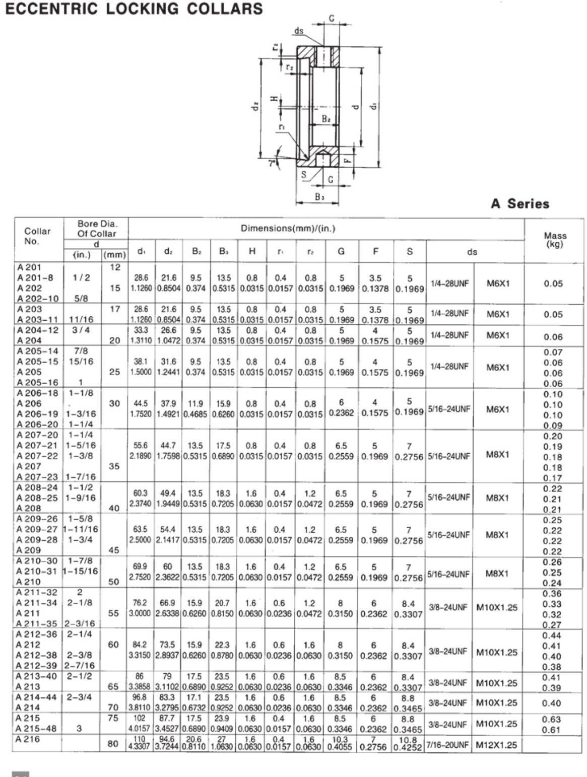
A-series collar tables cover metric and inch bore variants, with dimensions such as d1, d2, B2/B3, H, radii, G, F, S and the collar set-screw size.
How the eccentric lock works
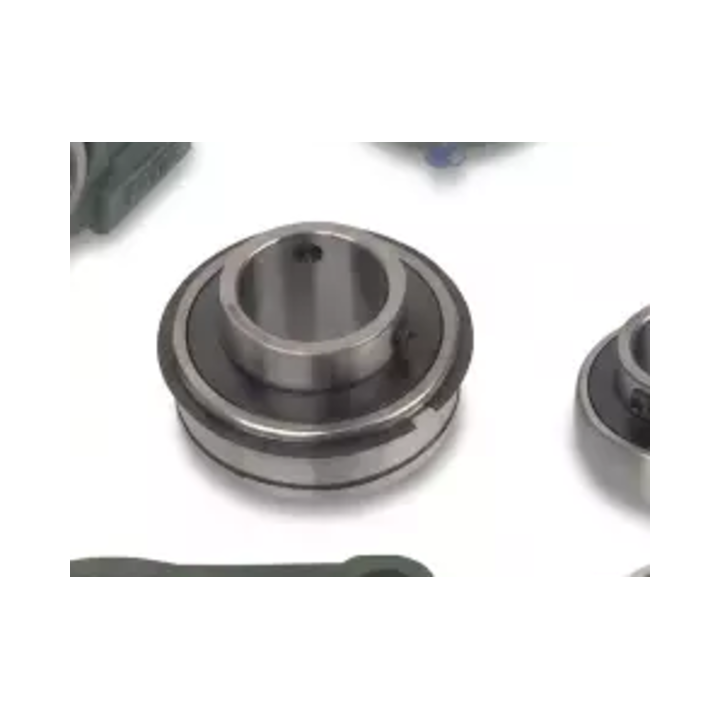
The inner ring of the compatible bearing has an eccentric extension. The collar has a matching eccentric bore. When the collar is rotated in the direction of shaft rotation, the two eccentric surfaces wedge together and grip the shaft. A set screw then retains the collar position.
What the A-series dimensions mean
The collar table does more than list bore. Outside diameters, widths and eccentric dimensions determine whether the collar physically matches the inner-ring extension. The set-screw size also changes across the range. Use the exact collar row for the intended insert rather than selecting a collar only by shaft diameter.
Installation procedure
- Confirm the bearing insert and A-series collar are the intended matching pair.
- Slide the bearing into its final shaft position and seat the collar on the eccentric extension.
- Rotate the collar in the direction of shaft rotation until it seats firmly against the eccentric surface.
- Tighten the collar set screw using the value specified for the actual collar/insert configuration.
- Rotate the shaft and verify the bearing/housing remains free before returning the machine to service.
Removal procedure
Loosen the collar set screw first. Then rotate the collar opposite the shaft-running direction to release the eccentric wedge. If corrosion or fretting has made the collar stubborn, use a proper collar tool or controlled non-damaging method; hammering the bearing or housing risks damaging the new seating surfaces.
Compatibility is series-specific
A-series numbers are intended to correspond with specific NA/SA/HC-style insert families and bore variants. Do not assume that an A205 collar fits every 25 mm insert on the market. The eccentric geometry and width have to match the bearing design.
What to send in an RFQ
| Information | Why it matters |
|---|---|
| Complete bearing model | Identifies insert family and size |
| Existing collar number | Best compatibility clue when readable |
| Shaft diameter | Confirms metric/inch bore |
| Photo of eccentric inner-ring extension | Shows locking construction |
| Rotation direction | Needed for correct collar locking during installation |
The collar and insert form one locking system
An eccentric collar works because its eccentric bore engages the matching eccentric extension on the insert. The collar number, insert family and shaft diameter therefore have to match. A collar that looks close but does not have the correct eccentric geometry should not be forced onto the bearing.
Installation and removal control
Seat the insert in the housing and place the collar on the eccentric extension. Rotate the collar in the intended shaft-rotation direction to engage the eccentric surfaces, then secure the collar set screw according to the applicable product instructions. For removal, loosen the screw and drive or rotate the collar in the opposite direction using an appropriate tool that does not damage the bearing or shaft.
Replacement checklist
Record collar number, insert model, bore, shaft direction of rotation, set-screw condition and available tool clearance. If the collar repeatedly loosens, inspect shaft fit, collar engagement and vibration rather than simply applying more tightening force.
Need a model checked against your machine? Send the dimensions with your RFQ.