How to Install a UCP Pillow Block Bearing: Step-by-Step Guide
A UCP unit is simple to mount only when the shaft, base and fasteners are prepared first. Most avoidable installation problems come from burrs, a damaged shaft, a distorted mounting surface, premature tightening or a locking method that is handled in the wrong sequence.
The procedure below is written for standard set-screw UCP units, with a separate step for eccentric-collar types. Exact shaft tolerances and housing-bolt torque still have to follow the ordered bearing configuration and the machine structure.
Tools and preparation
Prepare a calibrated torque wrench for the set screws, the correct hex key, a shaft measuring tool, clean lint-free cloths and the housing fasteners specified by the machine. Clean the shaft and remove raised burrs or corrosion that can damage the bore during assembly.
Check the mounting surface for flatness and debris. A commonly used shaft-fit reference for insert-bearing applications is an h9-type tolerance, but the final tolerance should be confirmed for the ordered unit, loading and speed rather than applied as a universal rule.
Step 1: position the housing on the support
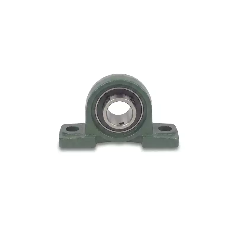
Place the pillow block on the support frame and install the mounting bolts finger-tight. At this stage the housing should still be able to settle into alignment. If the shaft uses two supports, place both housings before fully clamping either one so the pair can align to the actual shaft line.
Step 2: pass the shaft through the insert
Slide the clean shaft through the bearing bore without hammering the housing. Position the bearing at the required axial location and rotate the shaft by hand. Binding before the locking screws are tightened is a warning that the base, shaft or second support needs correction.
Step 3: lock a set-screw insert to the shaft
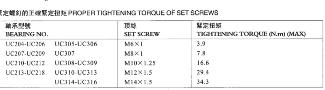
The supplied bearing-unit instructions use two set screws on the wide inner ring, arranged 120 degrees apart. Tighten them to the specified value for the actual insert series. Do not substitute the housing-bolt size for the set-screw size: these are different fasteners with different functions.
| Insert range | Set screw | Maximum tightening torque |
|---|---|---|
| EP-UC204–UC206 / UC305–UC306 | M6 x 1 | 3.9 N·m |
| EP-UC207–UC209 / UC307 | M8 x 1 | 7.8 N·m |
| EP-UC210–UC212 / UC308–UC309 | M10 x 1.25 | 16.6 N·m |
| EP-UC213–UC218 / UC310–UC313 | M12 x 1.5 | 29.4 N·m |
| EP-UC314–UC316 | M14 x 1.5 | 34.3 N·m |
Alternative step: eccentric locking collar
For an eccentric-collar family, seat the collar on the eccentric extension of the inner ring and rotate it in the direction of shaft rotation to lock the collar. Then tighten the collar set screw. Keep the collar and insert as a matched locking system; do not apply the set-screw UCP sequence to an eccentric unit.
Step 4: secure the housing and recheck free rotation
Once the bearing positions are established, tighten the housing mounting bolts according to the machine fastener specification, bolt grade and support material. Set-screw torque is specified separately from housing mounting-bolt torque; a universal mounting-bolt value should not be inferred from the insert data.
Rotate the shaft again after final clamping. It should turn without a new tight spot caused by the housing bolts pulling one support out of line.
Step 5: lubrication and start-up check
Insert-bearing units are supplied prelubricated, and standard cast-iron housings are equipped with grease fittings for relubrication. Whether additional grease is needed at commissioning depends on the ordered configuration and storage condition. Confirm the grease type before adding a different lubricant, because incompatible greases can compromise lubrication.
After start-up, monitor temperature, noise and vibration. A sudden rise in any of them is a reason to stop and recheck alignment, locking and grease quantity rather than simply adding more grease.
Common mistakes to avoid
- Using a hammer on the housing or inner ring to force the unit onto a damaged shaft.
- Fully tightening one housing before the shaft and second support have settled into alignment.
- Over-tightening set screws beyond the insert-series torque limit.
- Assuming any mounting-bolt torque applies regardless of bolt grade or support material.
- Adding an incompatible grease or overfilling the housing during the first service.
Alignment between two pillow blocks
Most shafts use more than one support, so installation is a system task. Place both housings on their mounting faces and allow the shaft to settle through the inserts before final base tightening. If one housing is fully clamped while the second is still being forced into position, the shaft can run under constant side load. That condition may show up as heat or noise even when the individual bearing is new.
Commissioning after installation
After the shaft-locking hardware and housing bolts are secured according to the applicable model or machine specification, rotate the assembly by hand where safe. During initial operation, watch temperature, vibration and seal condition. A small change as components seat is different from rapid heating, repeated fastener movement or a sharp rise in vibration. Those signs justify stopping and checking alignment, shaft fit, balance and grease condition before the machine reaches full duty.
Record the installation data
For repeat maintenance, record the bearing model, shaft diameter, locking torque used, housing fastener details and any alignment measurement. This creates a baseline for the next inspection and prevents a future technician from relying on an unverified “same as last time” assumption.
Need a model checked against your machine? Send the dimensions with your RFQ.